2. The Bridge Pin
One of the most essential aspects of how a tarhu works is the way in which the bridge drives the cone. This system relies on the bridge rotating around a fixed point, in which vibrations in one plane (in the direction of bowing) are transferred through 90 degrees to the cone.This pivot point is therefore a crucial component, simple as it is.
Tarhu bridges initially had two “feet” glued to the bridge - an active foot, or bridge stick (that passed through the neck to the top of the cone), and a passive foot (which was much shorter and sat on the neck……often in an oversize hole drilled in the neck).
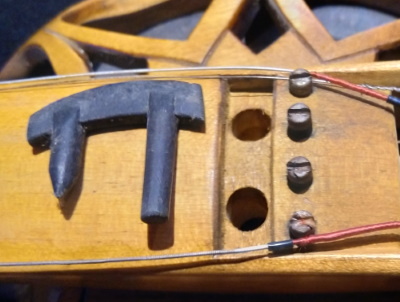
There was no adjustment of bridge-movement parameters in these early bridges - the position and length of the passive foot was pre-determined when the bridge was made. Experiments soon showed that the position of both bridge feet had quite an influence on sound, and so an adjustable system was devised in the late nineties. Rather than the passive foot being in the form of a stick glued to the bridge, the bridge instead rested on a spring steel pin that could be adjusted in several ways: it could be moved along the bottom of the bridge to different locations; the pillars supporting the pin could be moved in and out, reducing or increasing the amount of spring in the bridge system.
The pin therefore operates in a very similar way to a violin’s soundpost, whose location can be changed, thus increasing or decreasing the stiffness around the passive foot of the violin’s bridge. In the violin this level of adjustability is considered absolutely essential, as it is with tarhus. Inevitably each instrument is an individual, with its vibrating membrane having its own particular relationships between stiffness, mass and resonance. The best results can only be achieved from each instrument if the subtle relationships between bridge movement patterns (pin location) and bridge stiffness (pin effective length) can be minutely adjusted.
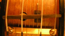
Here is the range through which adjustments can be made:

The pin is right at the treble edge of the bridge. The bridge pin pillars are fully open, providing the most flexibility

The pillars have been closed, increasing stiffness.
The location on the treble edge of the bridge is the most common one for type 2 cones (see Article #6)

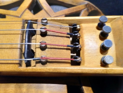
The pin has been moved towards the centre of the bridge, pillars fully open.

Pillars fully closed.
This location along the bridge is the most common position for type 1 cones.

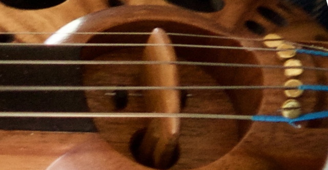
Pin is as far towards the centre of the bridge as it can go.
This pin location is the most common one for type 3 cones
For any cone type, all pin positions and all pillar positions can be explored…..however, the trend has unquestionably been for the pillar position to be more open than closed regardless of where the pin ends up being located - all forms of tarhu like having a bit of spring in the bridge system.
The other interesting trend is that for cones using a floating bridge (types 1 & 3), the sound usually becomes more interesting as the bridge pin is moved closer towards the centre of the bridge. Unfortunately, the sound also becomes more temperamental as the pin moves towards the centre, and so a compromise usually has to be reached between “interesting” and “smooth”. Similarly, pillars open is more interesting than pillars closed. As the pillars are opened further, a point is reached where power drops off and the instrument starts to feel “soggy”.
The length of the bridge pin needs to be sufficient that the excessive flexibility point can definitely be reached. If the area surrounding the bridge has restricted space for a longer pin, a pin of smaller diameter can be used - such a pin can be shorter yet still reach the “too soggy” point. Thinner pins are more temperamental to adjust - a smaller amount of adjustment has a greater affect on stiffness. String down-pressure can also bend a thin pin, which then makes adjustment more difficult. Thicker pins have the reverse problem - they have to be longer to achieve the same degree of flexibility.
Making a bridge pin

The pin is made from spring steel. The diameters used have ranged from 0.8 mm to 1.5 mm, with 1.2 mm being the preferred size. Spring steel wire is readily available from hobby shops that supply makers of model aircraft. Sewing needles are also a ready source of spring steel wire.
One end of the pin needs to be ground to a sharp point.

For the pillars the preferred material is buffalo horn. Hard wood can be used, but is more likely to split. Buffalo horn holds the pin firmly but is naturally greasy enough that the pillar will slide easily.

The block of buffalo horn is held in the drill-press vice and drilled with the sharpened pin. DON’T use a drill bit for this - if the pin is not a perfect fit it will rattle.

After the holes have been drilled the pillars are cut off the block, shaped and sanded. The pin is then checked for fit……if it is too tight, put the pin in the drill press and while it is spinning, run the pillars up and down the pin a few times until the desired amount of tension is achieved. Place the pillars on the pin and burr the ends of the pin so that the pillars can’t come off.